
Perfect Bedroom Setup with a Split Receptacle Circuit
How to Ensure One Outlet is Always On While Controlling the Other with a Switch

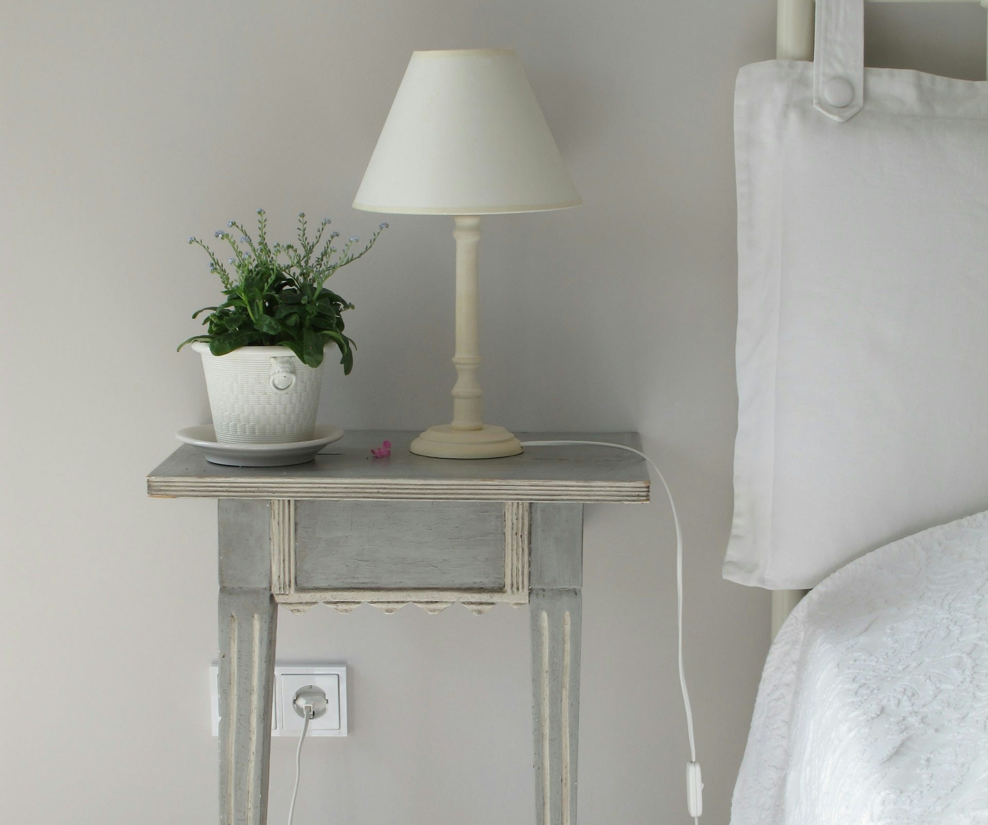
Wiring a circuit to connect a switch to a receptacle, where only one of the outlets is controlled by the switch, is a common setup in many homes. This is especially useful in rooms like bedrooms, where you might want one outlet to control a lamp while keeping the other outlet always energized for other appliances.
Let's walk through the steps and materials needed to complete this project.
Materials and Tools
14/2 Romex cable (for power supply)
14/3 Romex cable (for connecting switch and receptacle)
Wire nuts
Phillips and flathead screwdrivers
Wire stripper
Linesman pliers
Dykes
Cable ripper or razor
Voltage tester
Needle nose pliers (or similar)
Steps to Wire a Split Receptacle Circuit
1. Turn Off Power
Always start with safety. Turn off the power to the circuit at the main electrical panel. Use a voltage tester to ensure there's no power flowing to the outlets or switch.
2. Run 14/2 Romex Cable
Run a 14/2 Romex cable from the power source (breaker panel) to the switch box. The 14/2 cable has two conductors (black for hot, white for neutral) plus a bare copper ground wire.
3. Run 14/3 Romex Cable
From the switch box to the receptacle, run a 14/3 Romex cable. This cable has three conductors (black, red, and white) plus a bare ground wire. The extra wire (red) will be used to control the switched outlet.
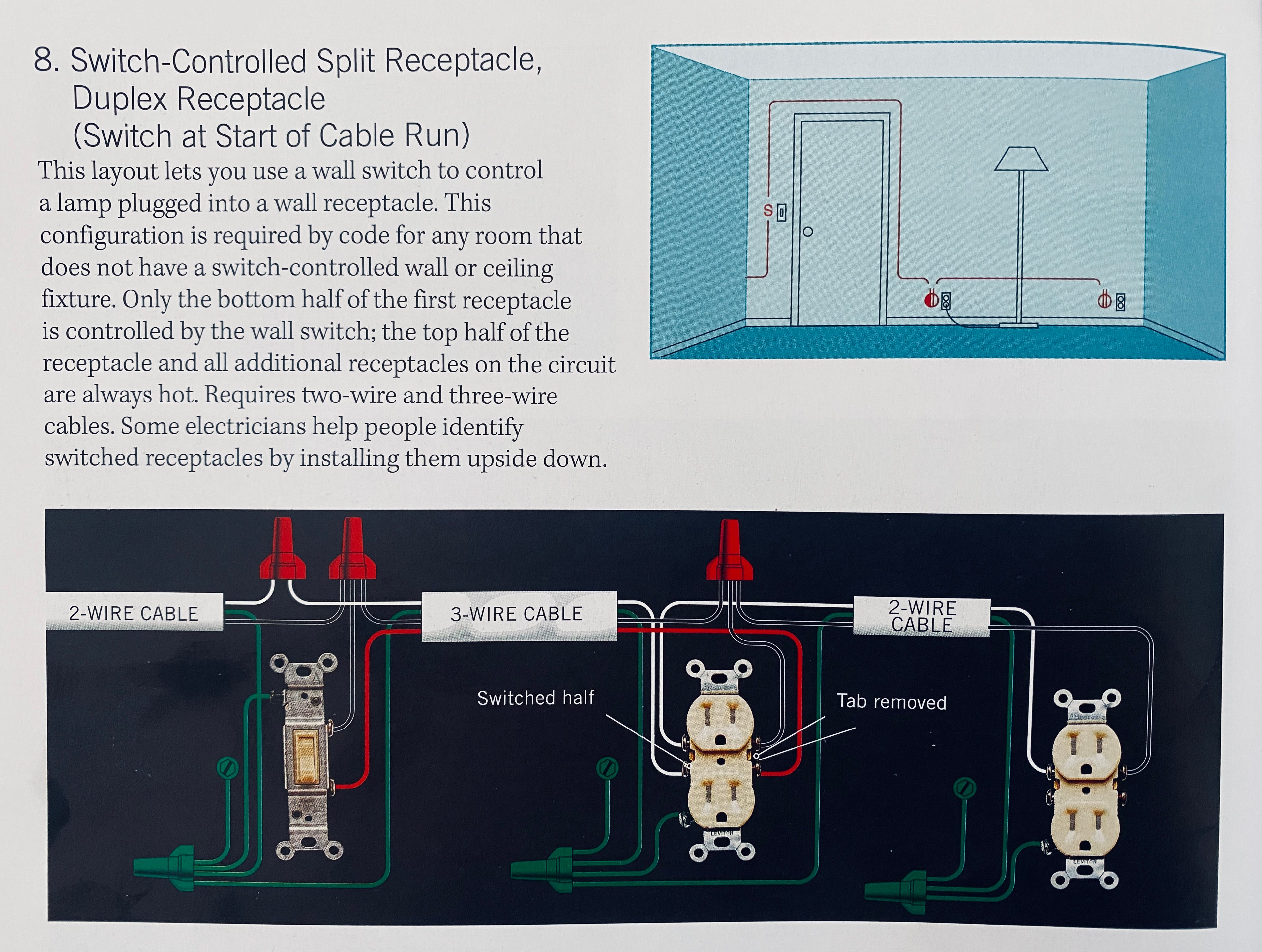
4. Connect Wires in the Switch Box
Black Wire: In the switch box, connect the black wires from both the 14/2 and 14/3 cables with a wire nut and add a pigtail that connects to the top terminal (or OFF position) on the switch.
Red Wire: Connect the red wire from the 14/3 cable to the bottom terminal (or the ON position) of the switch.
White Wires: Connect the white wires (from both cables) with a wire nut, to act as the neutral connection once it gets to the receptacle.
Ground Wires: Connect the ground wires from the 14/2 and 14/3 cable and attach a pigtail that extends to the grounding terminal on the switch and to the grounding screw in the switch box if it is a metal box.
5. Prepare the Receptacle
Locate the brass tab on the receptacle between the two hot terminal screws. This tab connects both outlets onto the same circuit. Using pliers, carefully break off this tab. This will allow one outlet to be controlled by the switch while the other remains always energized.
6. Connect Wires to the Receptacle
Black Wire: Attach the black wire from the 14/3 cable to the top hot terminal (always energized) of the receptacle.
Red Wire; Attach the red wire from the 14/3 cable to the bottom hot terminal (controlled by the switch) of the receptacle.
White Wire: Connect the white wire from the 14/3 cable to the neutral terminal of the receptacle.
Ground Wire: Attach the bare copper ground wire to the grounding terminal of the receptacle.
7. Final Checks and Power On
Double-check all your connections to ensure they are secure.
Carefully place the switch and receptacle back into their electrical boxes and secure them with screws.
Restore power at the main electrical panel and use a voltage tester to confirm that everything is working as expected. The bottom outlet should be controlled by the switch, and the top outlet should always be energized.